Operating Instructions for
CL and CLPB Series Self-pressurizing Dewars
Introduction
The container consists of an inner stainless steel cylinder securely supported in an outer jacket shell. The space between the inner and outer vessels contains a highly efficient insulation material and is evacuated.
Safety Devices
The inner liquid reservoir is protected by a relief valve and a rupture disc, both located on the manifold.
A combination evacuation port and relief device is provided to service the vacuum space. This protects the container in case of a leak in the inner reservoir. If this device vents, contact Cryofab; do not attempt to use the container or re-evacuate the insulation space.
Gauges
A pressure gauge is provided indicating inner vessel pressure. A liquid level gauge is provided to indicate approximate container contents.
Pressure Building System (CLPB only)
This container is equipped with an integral pressure building system to aid in liquid withdrawal. The pressure building system consists of the pressure building coil, the pressure building valve, and the pressure building regulator all connected in series.
The pressure building regulator maintains a preset vessel pressure during the liquid withdrawal as long as a sufficient liquid level is present in the container and the pressure building valve is open. If a different pressure setting is required, the pressure building regulator can be adjusted. To lower the setting, turn the adjusting screw counter-clockwise, to increase the setting turn clockwise.
NOTE
When the pressure building system is operating frost will appear near the bottom of the container.
Handling
These containers are designed for use in the upright position and should not be laid on their side. If a container must be lifted, hoist by means of the lifting slots in the halo ring struts. Do not attempt to lift by the handles or by means of slings around the shell.
Filling
These containers can be filled from a pressurized liquid source using the following procedure. Connect the liquid source to the fill/withdrawal valve (labeled liquid) using a suitable metal transfer hose or metal tubing. It is recommended that the transfer setup be equipped with a relief valve or other means of relieving pressure in the event that liquid is accidentally trapped between the fill/withdrawal valve and the liquid source valve. Open the vent valve (labeled vent) and the fill/withdrawal valve. To begin the transfer, open the liquid source valve. Keep the container pressure below the relief valve setting during filling; throttle the flow from the liquid source if necessary.
WARNING
During filling a cold stream of gas and or liquid will exit from the vent valve; keep clear of exiting stream.
When the container is filled to maximum capacity, liquid will start to exit from the vent valve; at that point shut off the liquid source valve. Disconnect the transfer hose and shut the fill/withdrawal and vent valves.
Withdrawal
Transferring liquid from the container is accomplished by the following procedure. Be sure the vent valve is closed and check the pressure gauge to see that the vessel pressure is adequate for the intended application. If additional pressurization is required, open the pressure building valve (if so equipped) to operate the integral pressure building coil. With the pressure building system functioning, the preset pressure will be maintained throughout the withdrawal, as long as a sufficient liquid supply is present to maintain the static head which drives the process.
Attach a suitable transfer line to the fill/withdrawal valve. If the transfer hose is connected in series with a downstream valve it is recommended that the transfer setup be equipped with a relief valve or other means of relieving pressure in the event that liquid is accidentally trapped between the fill/withdrawal valve and the downstream valve. Open the fill/withdrawal valve as far as necessary to obtain the desired flow rate. When the transfer is complete, close the fill/withdrawal valve and disconnect the transfer line. The pressure building valve may be left open, if desired, as this may, to a limited extent, determine the operating pressure of the vessel until the liquid is saturated.
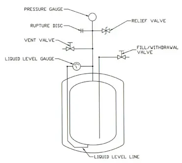
CL Series Piping Schematic
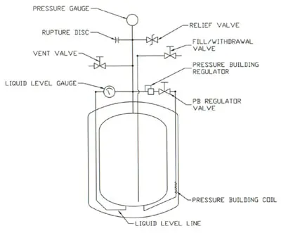
CLPB Piping Schematic
Changing Service
Although these containers can be supplied from the factory for LN2, LARG, or LOX service, do not attempt to change from the service for which the container was originally supplied without consulting the factory
Replacement Parts and Accessories
Click here to purchase replacement parts and accessories including valves, gauges and rupture discs.
VIEW/PRINT MANUAL